This section presents simple use cases that can be implemented using the provided Client Applications.
Bridging
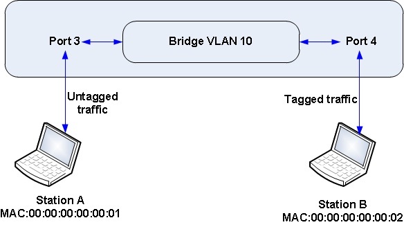
The figure below illustrates a simple bridging configuration. Two stations are connected to ports 3 and 4 of the switch and packets are bridged in the switch for these stations to communicate. Station A sends and receives untagged traffic while Station B sends and receives tagged traffic.
For traffic from station A to B.
- Add interface 3 in VLAN 10.
- # ./client_vlan --intf=3 --vlan=0x100a --mask=0x1fff
- Set VLAN 10 as the default VLAN on interface 3. This will classify an untagged packet received on this interface on VLAN 10.
- # ./client_vlan --intf=3 --vlan=0 --mask=0x0fff --newvlan=10
- Create L2 interface group on interface 4 and vlan 10 with pop vlan as 0 to send tagged packet.
- # ./client_group --groupid=0xa0004
- # ./client_group --groupid=0xa0004 --l2intfbktid=0 --outport=4 --popvlan=0
- Create a bridging entry referring the created L2 interface group. This creates an L2 entry for the given MAC on interface 4 on VLAN 10.
- # ./client_bridging --group=0xa0004 --dstmac=00:00:00:00:00:02 --vlan=10
For traffic from station B to A.
- Add interface 4 in VLAN 10.
- # - # ./client_vlan --intf=4 --vlan=0x100a --mask=0x1fff
- Create L2 interface group on interface 3 and vlan 10 with pop vlan as 1 to send untagged packet.
- # ./client_group --groupid=0xa0003
- # ./client_group --groupid=0xa0003 --l2intfbktid=0 --outport=3 --popvlan=1
- Create a bridging entry referring the created L2 interface group. This creates an L2 entry on for the given MAC interface 3 on VLAN 10.
- # ./client_bridging --group=0xa0003 --dstmac=00:00:00:00:00:01 --vlan=10
This configures the switching path between stations A and B.
IPv4 Unicast Routing
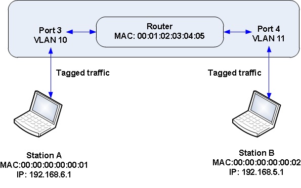
The figure below illustrates a simple IPv4 Unicast Routing configuration. Two stations are connected to ports 3 and 4 of the switch and packets are routed in the switch for these stations to communicate. The packets are routed between VLAN 10 and 11.
- Add interface 3 to vlan 10
- # ./client_vlan --intf=3 --vlan=0x100a --mask=0x1fff
- Add interface 4 to vlan 11
- # ./client_vlan --intf=4 --vlan=0x100b --mask=0x1fff
- Create Termination MAC flow on the ingress port on vlan 10. Termination MAC flow decides whether to switch or route a packet. 00:01:02:03:04:05 is the Router MAC.
- # ./client_termmac --intf=3 --vlan=10 --dstmac=00:01:02:03:04:05
- Create Termination MAC flow on the ingress port on vlan 11
- # ./client_termmac --intf=4 --vlan=11 --dstmac=00:01:02:03:04:05
- Create an L2 interface group on port 3 vlan 10
- # ./client_group --groupid=0xa0003
- # ./client_group --groupid=0xa0003 --l2intfbktid=0 --outport=3 --popvlan=0
- Create and L3 unicast group with reference group as L2 interface group
- # ./client_group --groupid=0x20000002
- # ./client_group --groupid=0x20000002 --l3ucastbktid=0 --l3ucastdstMac=00:00:00:00:00:01 --l3ucastsrcMac=00:01:02:03:04:05 --l3ucastrefGID=0xa0003 --l3ucastvlanId=11
- Create an L2 interface group on port 4 vlan 11
- # ./client_group --groupid=0xb0004
- # ./client_group --groupid=0xb0004 --l2intfbktid=0 --outport=4 --popvlan=0
- Create and L3 unicast group with reference group as L2 interface group
- # ./client_group --groupid=0x20000001
- # ./client_group --groupid=0x20000001 --l3ucastbktid=0 --l3ucastdstMac=00:00:00:00:00:02 --l3ucastsrcMac=00:01:02:03:04:05 --l3ucastrefGID=0xb0004 --l3ucastvlanId=11
- Create a Routing flow
- # ./client_routing --dstip4=192.168.5.1 --ether=0x0800 --prefix=32 --vlan=11 --setgroup=0x20000001
- # ./client_routing --dstip4=192.168.6.1 --ether=0x0800 --prefix=32 --vlan=10 --setgroup=0x20000002
This configures the Routing path between stations A and B.